4 Breadboard
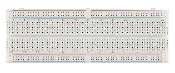
A breadboard is a device used to prototype electronic circuits without the need for soldering. It consists of a plastic board with rows of holes. In the central area, each group of five holes shares a metal strip; the centre gap separates the two groups in each numbered row. Different numbered rows are not connected. Along the sides are power rails marked + and -, typically used for the positive supply and ground. These markings do not supply power: the rails must be wired to a source. Each rail is separate, and some boards split the rails halfway along their length. When a component, such as a resistor, capacitor, or LED, is inserted into a hole on the breadboard, it makes contact with the metal strip that runs underneath the holes, which provides electrical connectivity between the components. This allows multiple components to be connected together to form a circuit. Breadboards are commonly used by hobbyists, students, and engineers to quickly prototype and test electronic circuits before they are soldered onto a printed circuit board.
Try it · Follow the hidden connections
Which holes are connected?
Click a hole to reveal every hole connected to it. Add a jumper to join two groups, or test a pair of holes for continuity.
Choose a hole to highlight its connected group.
Connected groupSelected hole / probe AB Second probe
Keyboard: Tab to the board, then to a hole; use arrow keys to move and Enter or Space to select. Escape cancels a first endpoint. On a small screen, scroll the board sideways.
a3–e3 share one metal strip.
No jumpers yet. Wires connect only at their ends; crossing wires do not join.
Load an example (replaces your jumpers)
What is connected inside a breadboard?
For each numbered row, a–e form one group of five and f–j form another. The centre gap separates the two groups. The next numbered row is a different group, even within the same lettered column.
Each side rail runs lengthwise, separately from the other rails. On a board with split rails, the upper and lower sections are separate too; a jumper can join them. Actual boards vary: check continuity on your unpowered board with a multimeter.
A shortened, 10-row teaching model. The + and − marks are labels, not voltage sources. This demo models metal connections and ideal jumper wires, not component behaviour, voltage or current. Each hole accepts one jumper end.
Very good tutorials on how to use a breadboard:
