10 Electronics Class 2
10.1 Digital read
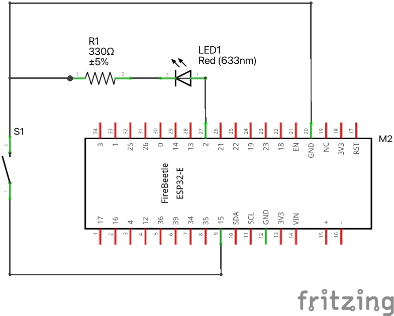
- Goal: Read button press and take an action (flash external LED).
Use the following code.
Download codeconst int buttonPin = A4; // Pin where the button is connected
const int ledPin = D9; // Pin where the LED is connected
// Variable to store the button state
int buttonState = 0;
void setup() {
// Initialize the LED pin as an output
pinMode(ledPin, OUTPUT);
// Initialize the button pin as an input
pinMode(buttonPin, INPUT_PULLUP); // Use the internal pull-up resistor
// Start serial communication for debugging (optional)
Serial.begin(115200);
}
void loop() {
// Read the state of the button
buttonState = digitalRead(buttonPin);
// Check if the button is pressed
if (buttonState == LOW) { // Assuming the button connects to ground when pressed
Serial.println("Button pressed! Blinking LED...");
// Blink the LED rapidly for 2 seconds (20 times per second)
unsigned long startMillis = millis();
while (millis() - startMillis < 2000) { // Run for 2000ms (2 seconds)
digitalWrite(ledPin, HIGH); // Turn the LED on
delay(50); // Wait for 50ms
digitalWrite(ledPin, LOW); // Turn the LED off
delay(50); // Wait for 50ms
}
// Optional: You can add a small delay here to debounce the button
delay(200); // Debounce the button for 200ms
}
// Add a small delay to avoid excessive readings
delay(50);
}see diagram
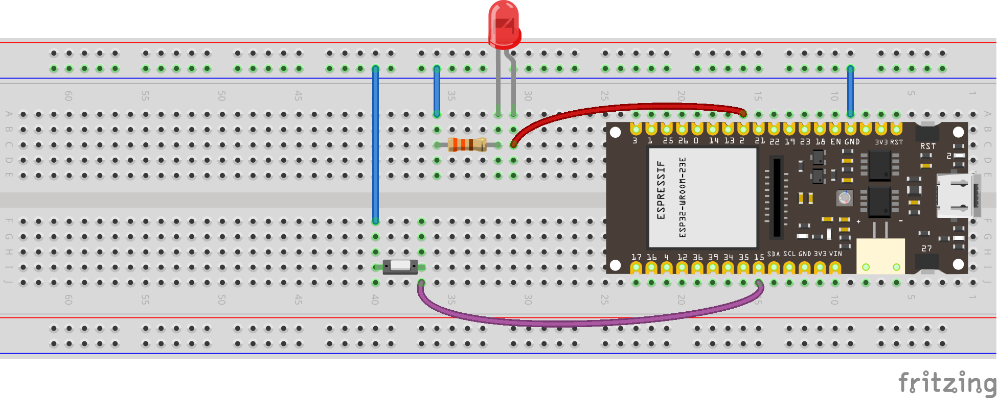
see wiring scheme
10.2 Reading an Analog Pin, convert to digital with built-in ADC
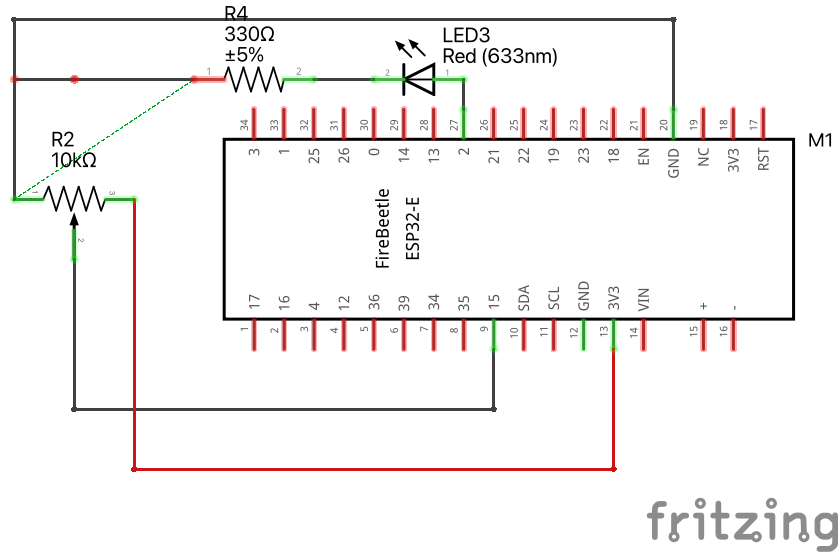
We will read the signal (middle) pin of the potentiometer, and use the 12-bit built-in Analog to Digital Converter.
Download codesee diagram
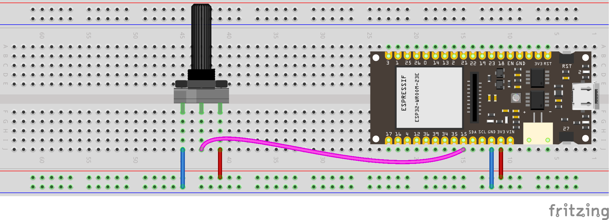
see wiring scheme
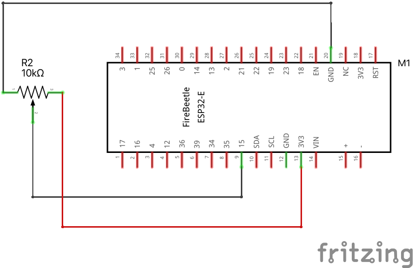
Why is the maximum number 4095? What does this have to do with 12-bits?
10.3 Reading an Analog Pin, convert to voltage
Use the same wiring as above. We will convert bits to volts now: \(4095 \text{ bits} = 3.3\text{ volts}\).
Download codeconst int analog_pin = A4; // Pin into which we connect the input voltage
int val ; // variable to store the value read
float voltage;
void setup() {
Serial.begin(115200); //
}
void loop() {
val = analogRead(analog_pin); // read the input pin
voltage = (3.3/4095)*val; // convert to voltage according to ADC
Serial.print("Voltage: ");
Serial.print(voltage); // print value
Serial.println(" V");
delay(100);
}10.4 PWM with ESP32
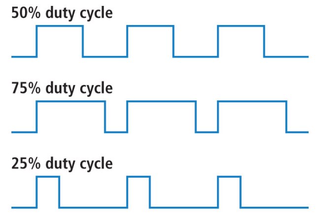
Pulse-width modulation (PWM) is a method of controlling the average power delivered by an electrical signal. The average value of voltage (and current) fed to the load is controlled by switching the supply between 0 and 100% at a rate faster than it takes the load to change significantly. PWM is a technique for getting analog results with digital means. Digital control is used to create a square wave, a signal switched between on and off. This on-off pattern can simulate voltages in between the full Vcc of the board and off by changing the portion of time the signal spends on versus the time that the signal spends off. PWM is used in many applications such as controlling motor speed, heat output of heaters and variable speed fan controllers.
Use the following code to activate LED pin with PWM, using the potentiometer as input.
Download codeconst int ledPin = D9; // the number of the LED pin
int analog_pin = A4; // Pin into which we connect the middle leg of the potentiometer
int val ; // variable to store the value read
// setting PWM properties
const int freq = 5000; // 5000 Hz
const int ledChannel = 0;
const int resolution = 12; // 12-bit resolution = between 0 and 4095
void setup(){
Serial.begin(115200);
// configure LED PWM functionalitites
ledcSetup(ledChannel, freq, resolution);
// attach the channel to the GPIO to be controlled
ledcAttachPin(ledPin, ledChannel);
}
void loop(){
val = analogRead(analog_pin); // read the input pin
Serial.println(val); // print value
ledcWrite(ledChannel, val);
delay(15); // update duty cycle parameters every 15 ms
}see diagram
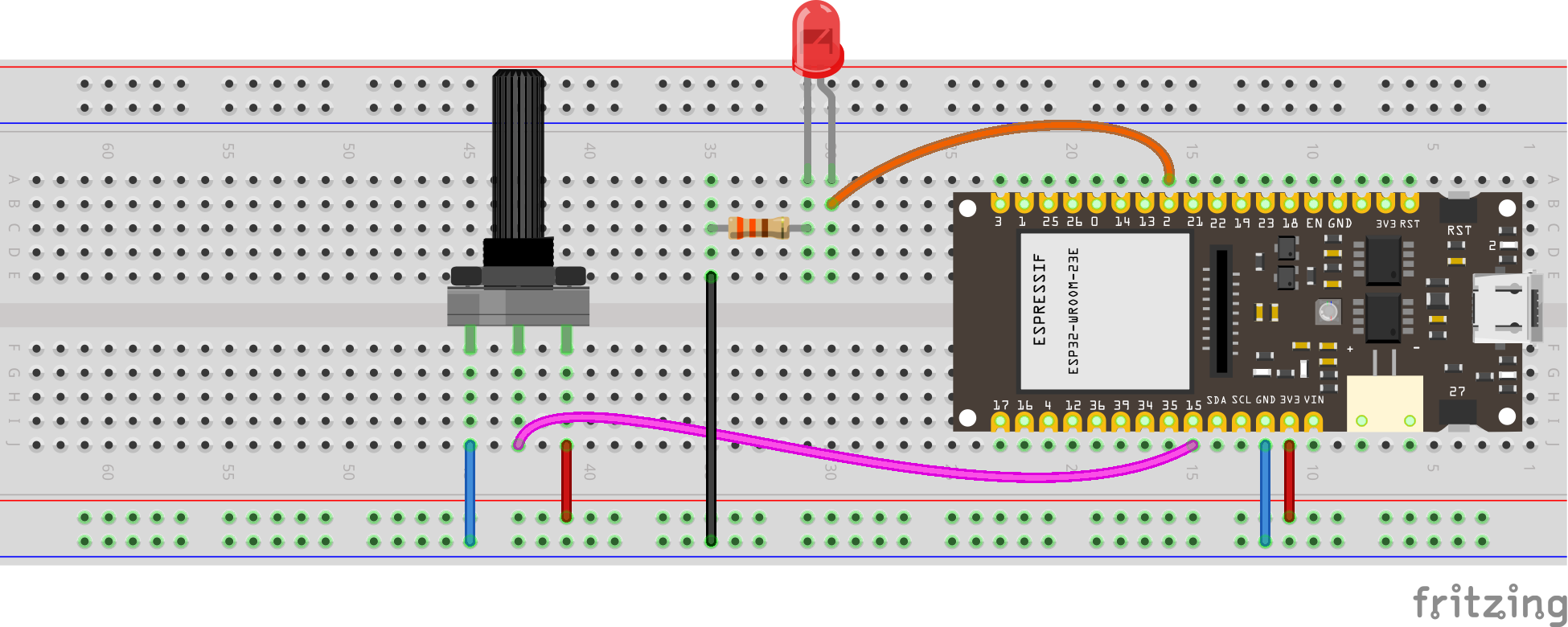
see wiring scheme
