17 Switches, Relays, Transistors
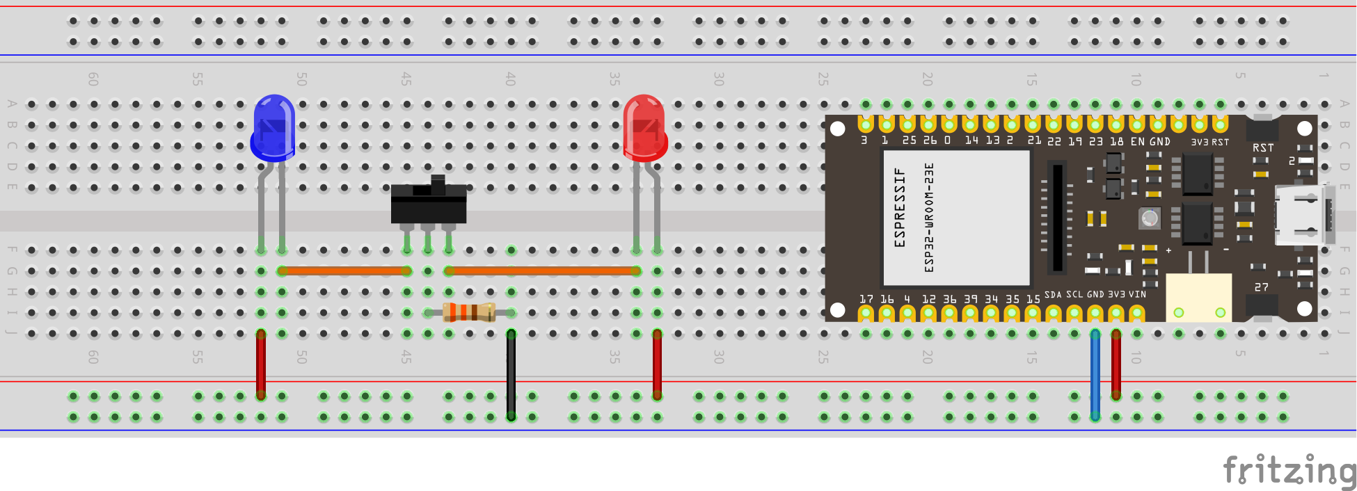
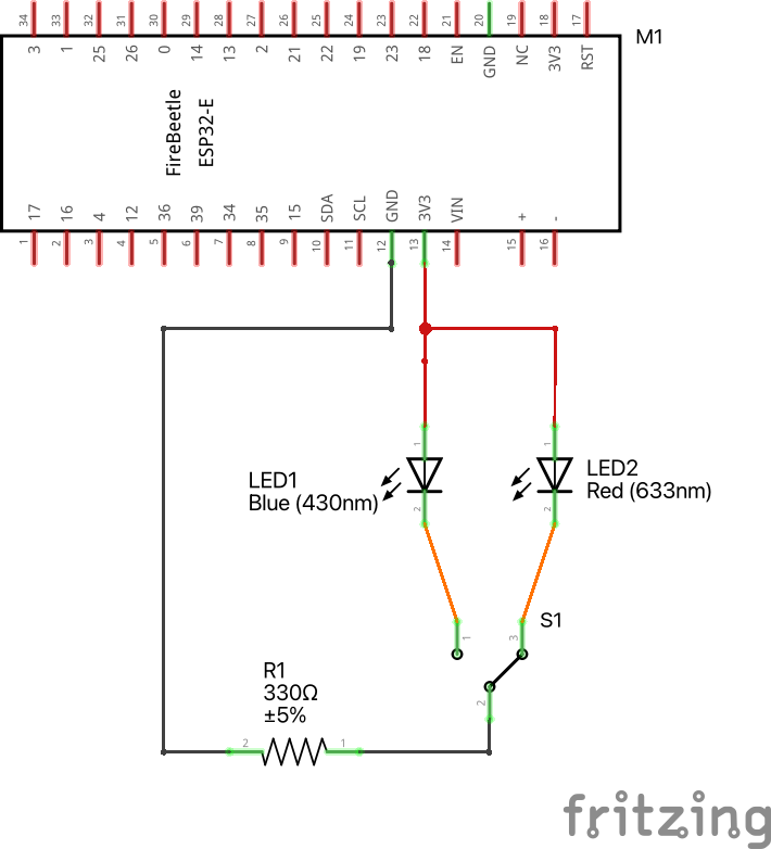
17.1 Toggle Switch
No code is needed here, we use the ESP32 just as a power source.
see diagram

see wiring scheme

17.2 Relay

A relay is an electromagnetic switch that opens and closes circuits electromechanically or electronically. A relatively small electric current that can turn on or off a much larger electric current operates a relay.
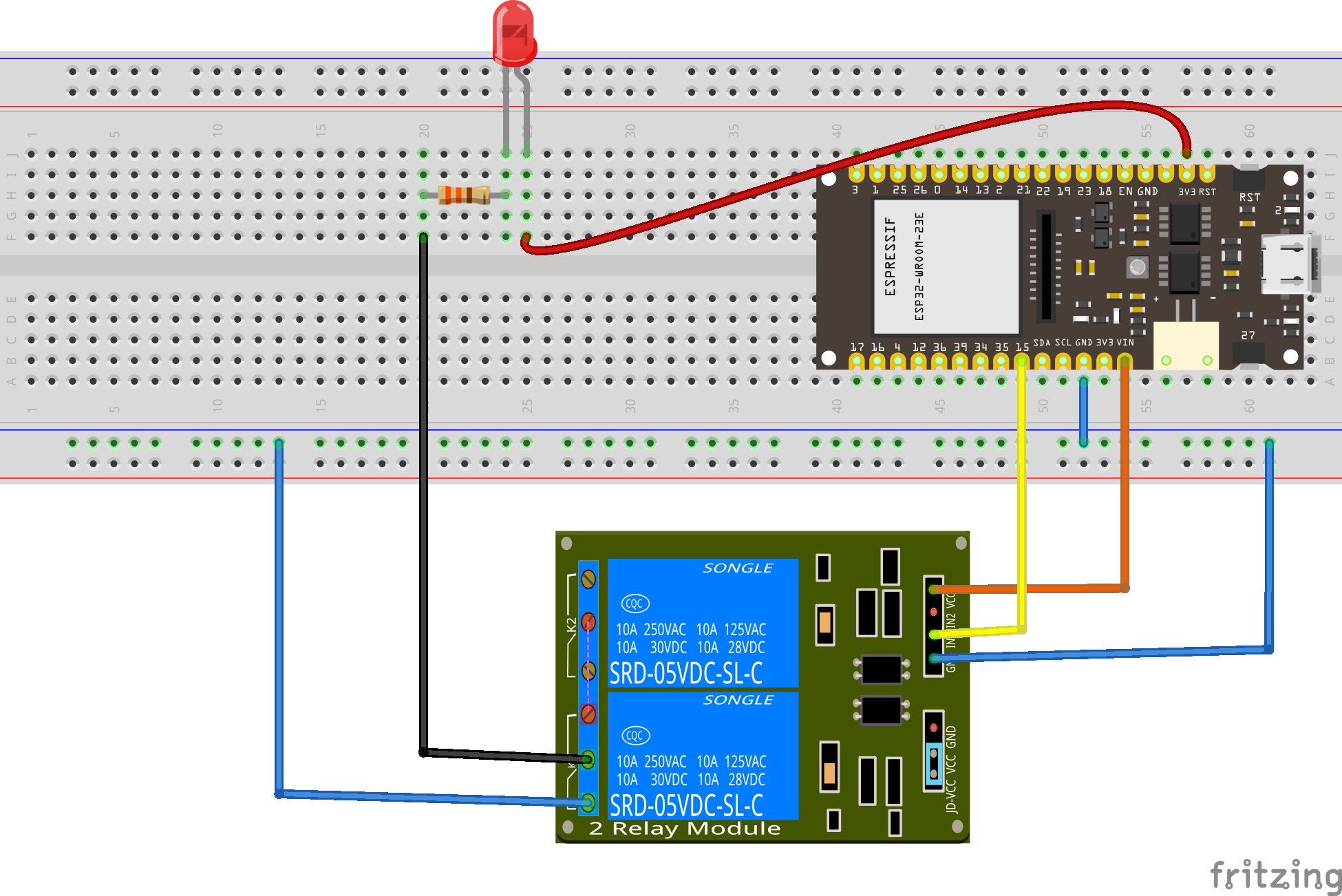
The right side in the image above has a set of four pins and a set of three pins. The top set consists of:
VCCshould be connected to the ESP32 VCC (5 volts)GNDconnects to the ESP32 GND.IN1andIN2are input pins, used to control the bottom and top relays, respectively, and should be connected to a GPIO pin in the ESP32.
The terminals on the left are connected to the load, the equipment that consumes power. The signal you send to the IN pins determines whether the relay is active or not. The relay is triggered when the input goes below about 2V. This means that you’ll have the following scenarios:
- Normally Closed (NC) configuration:
- HIGH signal – current is flowing
- LOW signal – current is not flowing
- Normally Open (NO) configuration:
- HIGH signal – current is not flowing
- LOW signal – current is flowing
Whether you use the NC or NO configuration, you should always connect one of them to the COM (common) terminal.
You should use a normally closed configuration when the current should be flowing most of the time, and you only want to stop it occasionally.
Use a normally open configuration when you want the current to flow occasionally (for example, to turn on a lamp occasionally).

The other set of three pins (on the left in the figure above) are GND, VCC, and JD-VCC. The JD-VCC pin powers the electromagnet of the relay. Notice that the module has a jumper cap connecting the VCC and JD-VCC pins; the one shown here is yellow, but yours may be a different color.
With the jumper cap on, the VCC and JD-VCC pins are connected. That means the relay electromagnet is directly powered from the ESP32 power pin, so the relay module and the ESP32 circuits are not physically isolated from each other.
Without the jumper cap, you need to provide an independent power source to power up the relay’s electromagnet through the JD-VCC pin. That configuration physically isolates the relays from the ESP32 with the module’s built-in optocoupler, which prevents damage to the ESP32 in case of electrical spikes.
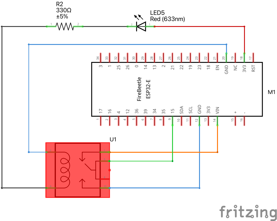
Let’s make an LED blink, but now using a relay. The code below is the same you used to make the LED blink, when it got its energy from pin A4. This time, we will use A4 to signal the relay to open or close the circuit.
int LED_pin = A4;

// the setup function runs once when you press reset or power the board
void setup() {
  // initialize digital pin LED_pin as an output.
  pinMode(LED_pin, OUTPUT);
}

// the loop function runs over and over again forever
void loop() {
  digitalWrite(LED_pin, HIGH);   // turn the LED on (HIGH is the voltage level)
  delay(3000);                       // wait for a second
  digitalWrite(LED_pin, LOW);    // turn the LED off by making the voltage LOW
  delay(1000);                       // wait for a second
}
see diagram

see wiring scheme

